Audio System Description - Overview

In this manual: Audio System Description - Overview
12 Volt Battery Component Location Index — 1A/T Differential Component Location Index — 1AC Power Outlet Component Location Index — 1Audio System Component Location Index — 1Automatic Dimming Mirrors Electrical Component Location Index — 1Blind Spot Information System/Cross Traffic Monitor Component Location Index — 1Bumpers Component Location Index — 1Climate Control System Component Location Index — 1Consoles Component Location Index — 1Cooling System Component Location Index — 1Cylinder Head Assembly Component Location Index — 1Dashboard Component Location Index — 1Driving Position Memory System (DPMS) Component Location Index — 1Engine Block Assembly Component Location Index — 1Entry Lights Control System Component Location Index — 1Exterior Lights Component Location Index — 1Fenderwell Component Location Index — 1Front and Rear Suspension Component Location Index — 1Fuel and Emissions Systems Component Location Index — 1Gauges Component Location Index — 1HandsFreeLink System Component Location Index — 1Heated Steering Wheel Component Location Index — 1Heating and A/C Systems Component Location Index — 1HomeLink Remote Control System Component Location Index — 1Hood Component Location Index — 1Ignition System Component Location Index — 1Interior Lights Component Location Index — 1Keyless Access System Component Location Index — 1Keyless/Power Door Locks/Security System Component Location Index — 1LaneWatch Component Location Index — 1Moonroof Electrical Component Location Index — 1Multiplex Integrated Control System Component Location Index — 1Navigation System Component Location Index — 1Parking and BackUp Sensor System Component Location Index — 1Power Lumbar Support Component Location Index — 1Power Seats Component Location Index — 1Power Windows Component Location Index — 1Rear A/C System Component Location Index — 1Rear Door Component Location Index — 1Rear Entertainment System Component Location Index — 1Reminder Systems Component Location Index — 1Safety Indicator System Component Location Index — 1Seat Belts Component Location Index — 1Seats Component Location Index — 1Second Row Seat with One-Touch Access Component Location Index — 1Shift Position Indicator Component Location Index — 1SRS Component Location Index — 1Starting System Component Location Index — 1Tailgate Component Location Index — 1Transfer Assembly Component Location — 1Turn Signal/Hazard Warning Lights Component Location Index — 1Ventilated Seats Component Location Index — 1Wipers/Washers Component Location Index — 1AC Inverter Unit Connector for Inputs and Outputs — 1Audio Unit Connector for Inputs and Outputs — 1Audio-Navigation Unit Connector for Inputs and Outputs — 1BD Player Unit Connector for Inputs and Outputs — 1Climate Control Unit Connector for Inputs and Outputs — 1DVD Player Unit Connector for Inputs and Outputs — 1EPS Control Unit Connector for Inputs and Outputs — 1HVAC Control Unit Connector for Inputs and Outputs — 1Keyless Access/TPMS Control Unit Connector for Inputs and Outputs — 1Media Hub Unit Connector for Inputs and Outputs — 1PCM Connector for Inputs and Outputs — 1Rear Controller and Screen Connector for Inputs and Outputs — 1SRS Unit Connector for Inputs and Outputs — 1Stereo Amplifier Connector for Inputs and Outputs — 1Under-Dash Fuse/Relay Box Connector for Inputs and Outputs — 1USB Adapter Connector for Inputs and Outputs — 11st Gear One-Way Clutch Inspection — 1A/C System Contamination Inspection — 1A/C System Inspection — 1A/T Differential Backlash Inspection — 1A/T Differential Carrier Bearing Preload Inspection — 1Air Cleaner Element Removal, Installation, and Inspection — 1APP Sensor Signal Inspection — 1ATF Pump Inspection — 1Ball Joint Boot Replacement and Inspection — 1Block and Piston Inspection — 1Brake Hose and Line Inspection — 1Brake Master Cylinder Inspection — 1Brake System Inspection and Test — 1BSI Radar Unit Aiming Inspection — 1Camshaft Inspection — 1Camshaft Timing Inspection — 1Catalytic Converter Inspection — 1Clutch Clearance Inspection — 1Connecting Rod and Crankshaft End Play Inspection — 1Countershaft 2nd Gear and 5th Gear Axial Clearance Inspection — 1Crankshaft and CKP Pulse Plate Removal, Installation, and Inspection — 1Cylinder Head Inspection for Warpage — 1Drive Belt Auto-Tensioner Inspection — 1Drive Belt Inspection — 1Engine Compression Inspection — 1Engine Oil Jet Bolt Inspection — 1Front Brake Disc Inspection — 1Front Brake Pad Inspection — 1Front Damper/Spring Disassembly, Reassembly, and Inspection — 1Fuel Line Inspection — 1Idle Speed Inspection — 1Idler Gear Shaft Installation Height Inspection and Adjustment — 1Ignition Timing Inspection — 1Over-Run Alternator Decoupler (OAD) Pulley Inspection — 1Parking Brake Inspection — 1PCV Valve Inspection — 1Propeller Shaft Inspection — 1Rear Brake Disc Inspection — 1Rear Brake Pad Inspection — 1Rear Damper/Spring Disassembly, Reassembly, and Inspection — 1Rear Differential Fluid Inspection and Replacement — 1Rocker Arm and Shaft Disassembly, Reassembly, and Inspection — 1Seat Belt Inspection — 1Secondary Shaft 2nd Gear and 5th Gear Axial Clearance Inspection — 1Secondary Shaft Installation Height Inspection and Adjustment — 1Spark Plug Inspection — 1Steering Column Inspection — 1Third Shaft 6th Gear Axial Clearance Inspection — 1Timing Belt Inspection — 1Transfer Assembly Inspection — 1Transfer Output Shaft Installation Height Inspection and Adjustment — 1Valve Inspection — 1Valve Stem-to-Guide Clearance Inspection — 1Water Pump Inspection — 1Wheel Bearing End Play Inspection — 1Wheel Runout Inspection — 1Danger/Warning/Caution Label Locations — 1Emergency Towing — 1Lift and Support Points — 1Lubricants and Fluids — 1Torque Specifications — 1Under-Hood Emission Control Label — 1VIN, Engine, (Motor), and Transmission Number Locations — 112 Volt Battery Fan Motor Test — 1A/C System Test — 1A/T Clutch Pressure Control Solenoid Valve A, B, C, and D Test — 1A/T Pressure Test — 1A/T Road Test — 1ACC Combination Switch Removal, Installation, and Test — 1Air Mix Control Motor/Mode Control Motor/Recirculation Control Motor Test — 1Audio Remote Switch Test — 1Blower Power Transistor Test — 1Brake Booster Test — 1Brake Fluid Level Switch Test — 1Brake Pedal Position Switch Test — 1Brake System Inspection and Test — 1D4 Switch Test — 1Dashlights Brightness Control Switch Test — 1Door Key Cylinder Switch Test — 1Door Lock Actuator Test — 1Door Lock Knob Switch Test — 1Door Outer Handle Lock Switch Test — 1Driver's Power Seat Adjustment Switch Test — 1Driver's Power Seat Motor Test — 1Driver's Power Tailgate Switch Test — 1Driver's Power Window Motor Test — 1Driving Position Memory Switch Test — 1ECON Switch Test — 1Engine Oil Pressure Test — 1Front Passenger's Power Seat Adjustment Switch Test — 1Front Passenger's Power Seat Motor Test — 1Front Passenger's Power Window Motor Test — 1Fuel Fill Door Opener Switch Test — 1Fuel Gauge Sending Unit Test — 1Fuel Pressure Test — 1Hazard Warning Switch Test — 1Heated Steering Wheel Switch Test — 1Heated Steering Wheel Temperature Sensor Test — 1Heated Windshield Wiper Area Switch Test — 1Heated Windshield Wiper Area Test — 1HFL Switch Test — 1HomeLink Switch Test — 1Intelligent Traction Management Switch Test — 1Keyless Access LF Antenna Function Test — 1Keyless Access System (Keyless Access Control Unit, Electric Steering Lock, and TPMS Control Unit) Input Test — 1Keyless/Power Door Locks/Security System (MICU, Door Multiplex Control Unit, and Front Passenger's Power Window Switch) Input Test — 1Line Pressure Solenoid Valve A Test — 1Low Fuel Indicator Test — 1Moonroof Motor-Control Unit Input Test — 1Moonroof Switch Test — 1Paddle Shifter Test — 1Park Pin Switch Test — 1Parking Brake Switch Test — 1Power Lumbar Support Motor Test — 1Power Lumbar Support Switch Test — 1Power Mirror Actuator Test — 1Power Mirror Switch Test — 1Power Relay Test — 1Power Tailgate Closer Motor Test — 1Power Tailgate Inside Switch Test — 1Power Tailgate Latch/Ratchet Switch Test — 1Power Tailgate Motor Test — 1Power Tailgate Pinch Sensor Test — 1Radiator and A/C Condenser Fan Motor Test — 1RDM Switch Removal, Installation, and Test — 1Rear Blower Power Transistor Test — 1Rear Differential Clutch Test — 1Rear HVAC Control Motor Test — 1Rear Power Window Motor Test — 1Rear Power Window Switch Test — 1Roof Console Module Test — 1Seat Heater Switch Test — 1Seat Heater Test - Ventilated Seats — 1Seat Heater Test — 1Second Row Seat One-Touch Access Switch Test — 1Security Hood Switch Test — 1Select/Reset/Information Switch Test — 1Shift Lock Solenoid Test — 1Shift Solenoid Valve C Test — 1Snow Switch Test — 1Stall Speed Test — 1Starter Solenoid Test — 1Steering Heater Test — 1Sunlight Sensor Test — 1Sunshade Switch Test — 1Tailgate Latch Switch Test — 1Tailgate Outer Handle/Lock Switch Test — 1Tailgate Release Actuator Test — 1Transmission Range Switch Test — 1Variable Cylinder Management Rocker Arm Test — 1Ventilated Seat Switch Test — 1Washer Motor Test — 1Wiper Motor Test — 12nd Row Center Console Removal and Installation — 112 Volt Battery Duct Removal and Installation — 112 Volt Battery Removal and Installation — 112 Volt Battery Terminal Disconnection and Reconnection — 1A/C Compressor Clutch Check — 1A/C Refrigerant Leak Check — 1A/C Refrigerant Oil Replacement — 1A/C Refrigerant Recovery/Evacuation/Charging — 1A/C System Noise Check — 1A/T Differential Carrier Bearing Replacement — 1A/T Oil Seal Replacement — 1A/C Compressor Relief Valve Removal and Installation — 1A/C Compressor Removal and Installation — 1A/C Condenser Removal and Installation — 1AC Inverter Unit Removal and Installation — 1AC Power Outlet Removal and Installation — 1ACC Combination Switch Removal, Installation, and Test — 1Accelerator Pedal Module Removal and Installation — 1A/F Sensor Removal and Installation — 1Air Cleaner Element Removal, Installation, and Inspection — 1Air Cleaner Removal and Installation — 1Air Mix Control Motor/Mode Control Motor/Recirculation Control Motor Removal and Installation — 1Alternator Removal and Installation — 1Ambient Light Removal, Installation, and Test — 1AM/FM Antenna Amplifier Removal and Installation — 1ANC/Active Sound Control Microphone Removal and Installation — 1ANC/Active Sound Control Unit Removal and Installation — 1A/T Differential Carrier, Final Driven Gear, and Transfer Drive Gear Removal and Installation — 1A/T Hydraulic Control Unit Removal and Installation — 1ATF Filter Removal and Installation — 1ATF Hose Removal and Installation — 1ATF Level Check — 1ATF Replacement — 1ATF Temperature Sensor Removal and Installation — 1ATF Warmer Removal and Installation — 1Audio Remote Switch Removal and Installation — 1Audio Unit Removal and Installation — 1Audio-Navigation Unit Removal and Installation — 1Automatic Lighting/Rain Sensor Removal and Installation — 1Automatic Transmission Removal and Installation — 1Auxiliary Jack Assembly Removal and Installation — 1Ball Joint Boot Replacement and Inspection — 1Ball Joint Removal — 1BD Player Unit Removal and Installation — 1Beverage Holder Light Removal and Installation — 1Blower Unit Removal and Installation — 1Brake Booster Pressure Sensor Removal and Installation — 1Brake Hose Removal and Installation — 1Brake Master Cylinder Removal and Installation — 1Brake Pedal Position Switch Removal and Installation — 1BSI Alert Indicator Removal and Installation — 1BSI Radar Unit Removal and Installation — 1Cable Reel Removal and Installation — 1Camshaft Oil Seal Replacement In Car — 1Camshaft Pulley Removal and Installation — 1Camshaft Removal and Installation — 1Cargo Area Accessory Power Socket Removal and Installation — 1Cargo Area Light Removal, Installation, and Test — 1Carpet Removal and Installation — 1CD Player Unit Removal and Installation — 1Center Console Panel Removal and Installation — 1Center Console Rear Trim Removal and Installation — 1Center Console Removal and Installation — 1Center Console Shutter Removal and Installation — 1Center Console Side Cover Removal and Installation — 1Center Console Side Panel Removal and Installation — 1CKP Sensor Removal and Installation — 1CMBS OFF Switch Removal, Installation, and Test — 1Combination Light Switch Removal, Installation, and Test — 1Connecting Rod Bearing Replacement — 1Console Accessory Power Socket Removal and Installation — 1Console Box Light Removal and Installation — 1Coolant Replacement — 1Cowl Cover Removal and Installation — 1Crankshaft and CKP Pulse Plate Removal, Installation, and Inspection — 1Crankshaft Main Bearing Replacement — 1Crankshaft Pulley Removal and Installation — 1Cruise Control Combination Switch Removal, Installation, and Test — 1Cylinder Head Cover Removal and Installation — 1Cylinder Head Removal and Installation — 1Dashboard Center Lower Panel Removal and Installation — 1Dashboard Center Middle Trim Removal and Installation — 1Dashboard Center Speaker Trim Removal and Installation — 1Dashboard Meter Visor Removal and Installation — 1Dashboard Removal and Installation — 1Dashboard Side Lid Removal and Installation — 1Dashboard/Steering Hanger Beam Removal and Installation — 1Dashlights Brightness Control Switch Removal and Installation — 1Door Courtesy Light Removal and Installation — 1Door Pocket Light Removal and Installation — 1Drive Belt Auto-Tensioner Removal and Installation — 1Drive Plate Removal and Installation — 1Driver's Airbag Removal and Installation — 1Driver's Dashboard Lower Cover Removal and Installation — 1Driver's Power Seat Adjustment Switch Removal and Installation — 1Driver's Seat Position Sensor Removal and Installation — 1Driving Position Memory Switch Removal and Installation — 1DVD Player Unit Removal and Installation — 1ECT Sensor 1 Removal and Installation — 1EGR Pipe Removal and Installation — 1Emblem/Sticker Removal and Installation — 1Engine Block Sealing Bolt Removal and Installation — 1Engine Oil Filter Feed Pipe Removal and Installation — 1Engine Oil Filter Removal and Installation — 1Engine Oil Jet Replacement — 1Engine Oil Pan Removal and Installation — 1Engine Oil Pump Removal and Installation — 1Engine Oil Replacement — 1Engine Removal and Installation — 1Engine Start/Stop Switch Removal and Installation — 1EPS Motor/Control Unit Removal and Installation — 1EVAP Canister Purge Valve Removal and Installation — 1Evaporator Core Removal and Installation — 1Evaporator Expansion Valve Removal and Installation — 1Evaporator Temperature Sensor Removal, Installation, and Test — 1Exhaust Pipe and Muffler Removal and Installation — 1Exterior Lights Bulb Removal and Installation — 1Fog Light Removal and Installation — 1Front Accessory Power Socket Removal and Installation — 1Front Brake Disc Removal and Installation — 1Front Brake Pad Removal and Installation — 1Front Bulkhead Brace Removal and Installation — 1Front Bulkhead Cover Removal and Installation — 1Front Bumper Air Spoiler Removal and Installation — 1Front Bumper Center Upper Beam Removal and Installation — 1Front Bumper Lower Trim Removal and Installation — 1Front Bumper Removal and Installation — 1Front Bumper Side Trim Removal and Installation — 1Front Corner Sensor Removal and Installation — 1Front Damper/Spring Removal and Installation — 1Front Door Checker Removal and Installation — 1Front Door Gap Seal Removal and Installation — 1Front Door Glass Removal and Installation — 1Front Door Latch Removal and Installation — 1Front Door Lower Trim Removal and Installation — 1Front Door Outer Handle Removal and Installation — 1Front Door Outer Molding Removal and Installation — 1Front Door Panel Removal and Installation — 1Front Door Regulator Removal and Installation — 1Front Door Sash Outer Trim Removal and Installation — 1Front Door Weatherstrip Removal and Installation — 1Front Driveshaft Removal and Installation — 1Front Engine Mount Removal and Installation — 1Front Fender Fairing Removal and Installation — 1Front Fog Light Bulb Removal and Installation — 1Front Grille Trim Removal and Installation — 1Front Individual Map Light Removal, Installation, and Test — 1Front Knuckle/Hub/Wheel Bearing Replacement — 1Front Lower Arm Compliance Bush Removal and Installation — 1Front Lower Arm Removal and Installation — 1Front Passenger's Airbag Cutoff Indicator Removal and Installation — 1Front Passenger's Power Seat Adjustment Switch Removal and Installation — 1Front Passenger's Seat Rail Removal and Installation — 1Front Passenger's Weight Sensor Operation Check After Replacing Front Passenger's Seat Component(s) — 1Front Passenger's Weight Sensor Output Check After a Vehicle Collision — 1Front Passenger's Weight Sensor Removal and Installation — 1Front Passenger's Weight Sensor Unit Operation Check — 1Front Passenger's Weight Sensor Unit Removal and Installation — 1Front Power Window Motor Removal and Installation — 1Front Rocker Arm Oil Control Valve Removal and Installation — 1Front Seat Belt Buckle Removal and Installation — 1Front Seat Belt Removal and Installation — 1Front Seat Cushion Blower Removal and Installation — 1Front Seat Frame Removal and Installation — 1Front Seat Lumbar Support Removal and Installation — 1Front Seat Recline Cover Removal and Installation — 1Front Seat Removal and Installation — 1Front Seat Slide Lever Removal and Installation — 1Front Seat-Back Blower Removal and Installation — 1Front Seat-Back Cover Removal and Installation — 1Front Stabilizer Bar Removal and Installation — 1Front Stabilizer Link Removal and Installation — 1Front Suspension Stroke Sensor Removal and Installation — 1Front Wheel Arch Protector Removal and Installation — 1Fuel Cap Adapter Removal and Installation — 1Fuel Fill Door Opener Switch Removal and Installation — 1Fuel Line/Quick-Connect Fitting Removal and Installation — 1Fuel Tank Guard Removal and Installation — 1Fuel Tank Unit Removal and Installation — 1Gauge Control Module Removal and Installation — 1Glove Box Light Removal and Installation — 1Grab Handle Removal and Installation — 1Headlight Leveling Control Unit Removal and Installation — 1Headlight Removal and Installation — 1Heated Steering Wheel Control Unit Removal and Installation — 1Heated Steering Wheel Switch Removal and Installation — 1Heater Unit/Core Removal and Installation — 1HFL Switch Removal and Installation — 1High Mount Brake Light Removal and Installation — 1HomeLink Unit Removal and Installation — 1Hood Insulator Removal and Installation — 1Hood Opener Cable Removal and Installation — 1Horn Removal, Installation, and Test — 1Humidity/In-Car Temperature Sensor Removal, Installation, and Test — 1HVAC Control Unit Removal and Installation — 1Idle Stop Off Switch Removal, Installation, and Test — 1Ignition Coil and Spark Plug Removal and Installation — 1Injector Control Module Removal and Installation — 1Injector Removal and Installation — 1Inner Taillight Removal and Installation — 1Input Shaft (Mainshaft) Speed Sensor Removal and Installation — 1Intake Air Resonator Removal and Installation — 1Intake Manifold Removal and Installation — 1Intelligent Traction Management Switch Removal and Installation — 1Interior Light Switch Removal, Installation, and Test — 1Interior Trim Removal and Installation - Cargo Areas — 1Interior Trim Removal and Installation - Door Areas — 1Interior Trim Removal and Installation - Pillar Areas — 1Interior Trim Removal and Installation - Rear Side Area — 1Interior Trim Removal and Installation - Tailgate Areas — 1Intermediate Shaft Removal and Installation — 1i-VTM Control Unit Removal and Installation — 1Keyless Access LF Antenna (Front Interior) Removal and Installation — 1Keyless Access LF Antenna/Initiator (Left-Front) Removal and Installation — 1Keyless Access LF Antenna/Initiator (Right-Front) Removal and Installation — 1Keyless Access Remote Removal, Installation, and Test — 1Keyless Access/TPMS Control Unit Removal and Installation — 1Knock Sensor 1 (Bank 1) and Knock Sensor 2 (Bank 2) Removal and Installation — 1LaneWatch Camera Removal and Installation — 1License Plate Light Removal and Installation — 1LKAS Switch Removal, Installation, and Test — 1MAF Sensor/IAT Sensor Removal and Installation — 1MAP Sensor Removal and Installation — 1Middle Floor Undercover Removal and Installation — 1Mirror Holder Removal and Installation — 1Mirror Housing Cover Removal and Installation — 1Mis-Fuel Inhibit Device Removal and Installation — 1Moonroof Drain Channel Removal and Installation — 1Moonroof Drain Channel Slider and Cable Assembly Removal and Installation — 1Moonroof Frame and Drain Tube Removal and Installation — 1Moonroof Glass Removal and Installation — 1Moonroof Glass Roof Seal Removal and Installation — 1Moonroof Motor-Control Unit Removal and Installation — 1Moonroof Switch Removal, Installation, and Test — 1Multipurpose Camera Unit Removal and Installation — 1Output Shaft (Countershaft) Speed Sensor Removal and Installation — 1Outside Air Temperature Sensor Removal, Installation, and Test — 1Over-Run Alternator Decoupler (OAD) Pulley Removal and Installation — 1Paddle Shifter Removal and Installation — 1Panoramic Glass Roof Frame Removal and Installation — 1Panoramic Glass Roof Sunshade Removal and Installation — 1Panoramic Glass Roof Sunshade Trim Removal and Installation — 1Park Pin Switch Removal and Installation — 1Parking Brake Cable Removal and Installation — 1Parking Brake Pedal Removal and Installation — 1Parking Brake Shoe Removal and Installation — 1Passenger's Dashboard Trim Panel Removal and Installation — 1PCM Removal and Installation — 1Piston, Ring, Pin, and Connecting Rod Removal and Installation — 1Power Lumbar Support Switch Removal and Installation — 1Power Mirror Removal and Installation — 1Power Mirror Retract Actuator Removal and Installation — 1Power Mirror Switch Removal and Installation — 1Power Steering Assist Check — 1Power Tailgate Inside Switch Removal and Installation — 1Propeller Shaft Removal and Installation — 1Pulley End Crankshaft Oil Seal Replacement - In Car — 1Quarter Glass Removal and Installation — 1Radiator and A/C Condenser Fan, Motor, and Shroud Removal and Installation — 1Radiator Removal and Installation — 1RDM Switch Removal, Installation, and Test — 1Rear Air Outlet Removal and Installation — 1Rear Blower Motor Removal and Installation — 1Rear Brake Caliper Removal and Installation — 1Rear Brake Disc Removal and Installation — 1Rear Brake Pad Removal and Installation — 1Rear Bumper Lower Face Removal and Installation — 1Rear Bumper Skid Trim Removal and Installation — 1Rear Bumper Trim Removal and Installation — 1Rear Control Arm Removal and Installation — 1Rear Controller and Screen Removal and Installation — 1Rear Damper/Spring Removal and Installation — 1Rear Differential Breather Box and Hose Removal and Installation — 1Rear Differential Fluid Pressure Sensor Removal and Installation — 1Rear Differential Pump Motor Removal and Installation — 1Rear Door Checker Removal and Installation — 1Rear Door Glass and Regulator Removal and Installation — 1Rear Door Glass Outer Weatherstrip Removal and Installation — 1Rear Door Latch Removal and Installation — 1Rear Door Lower Trim Removal and Installation — 1Rear Door Outer Handle Removal and Installation — 1Rear Door Panel Removal and Installation — 1Rear Door Rear Sash Outer Trim Removal and Installation — 1Rear Door Sunshade Removal and Installation — 1Rear Door Weatherstrip Removal and Installation — 1Rear Driveshaft Removal and Installation — 1Rear Engine Mount Removal and Installation — 1Rear Evaporator Temperature Sensor Removal, Installation, and Test — 1Rear Individual Map Light Removal, Installation, and Test — 1Rear Knuckle/Hub Bearing Unit Removal and Installation — 1Rear License Trim Removal and Installation — 1Rear Lower Arm B Removal and Installation — 1Rear Map Light Removal, Installation, and Test — 1Rear Power Window Switch Removal and Installation — 1Rear Safing Sensor Removal and Installation — 1Rear Stabilizer Bar Removal and Installation — 1Rear Stabilizer Link Removal and Installation — 1Rear Suspension Stroke Sensor Removal and Installation — 1Rear Upper Arm Removal and Installation — 1Rear Wheel Arch Protector Removal and Installation — 1Rear Window Removal and Installation — 1Rearview Camera Removal and Installation — 1Relay Circuit Board Removal, Installation, and Test — 1Rocker Arm Assembly Removal and Installation — 1Rocker Arm Oil Pressure Sensor Removal and Installation — 1Rocker Arm Oil Pressure Switch A (Bank 1) and Rocker Arm Oil Pressure Switch B (Bank 1) Removal and Installation — 1Roof Antenna Removal and Installation — 1Roof Glass Removal and Installation — 1Roof Molding Removal and Installation — 1Roof Rail Removal and Installation — 1SD Card Removal and Installation — 1Seat Belt Shoulder Anchor Adjuster Removal and Installation — 1Seat Heater Replacement — 1Seat Heater Switch Removal and Installation — 1Second Row Seat Armrest Cover Removal and Installation — 1Second Row Seat Armrest Panel Removal and Installation — 1Second Row Seat Armrest Removal and Installation — 1Second Row Seat Belt Buckle Removal and Installation — 1Second Row Seat Belt Removal and Installation — 1Second Row Seat Cushion Cover Removal and Installation — 1Second Row Seat Cushion Cover Removal and Installation — 1Second Row Seat Frame Removal and Installation — 1Second Row Seat Heater Control Unit Removal and Installation — 1Second Row Seat One-Touch Access Actuator Removal, Installation, and Test — 1Second Row Seat One-Touch Access Switch Removal and Installation — 1Second Row Seat Recline Cover Removal and Installation — 1Second Row Seat Removal and Installation — 1Second Row Seat-Back Cover Removal and Installation — 1Second Row Seat-Back Recline Cable Removal and Installation — 1Secondary HO2S Removal and Installation — 1Secondary Valve Body Removal and Installation — 1Select/Reset/Information Switch Removal and Installation — 1Shift Cable Removal and Installation — 1Shift Lever Removal and Installation — 1Shift Solenoid Valve C Removal and Installation — 1Side Airbag Removal and Installation — 1Side Curtain Airbag Removal and Installation — 1Side Engine Mount Removal and Installation — 1Side Impact Sensor (First) Removal and Installation — 1Side Impact Sensor (Second) Removal and Installation — 1Side Sill Panel Removal and Installation — 1Snow Switch Removal and Installation — 1Speaker Removal, Installation, and Test — 1SRS Component Replacement/Inspection After Deployment — 1SRS Unit Removal and Installation — 1Starter Removal, Installation, and Performance Test — 1Steering Angle Sensor Removal and Installation — 1Steering Column Cover Removal and Installation — 1Steering Column/EPS Control Unit Removal and Installation — 1Steering Gearbox Mount Cushion Replacement — 1Steering Gearbox Removal and Installation — 1Steering Lock Removal and Installation — 1Steering Rack End Removal and Installation — 1Steering Shaft Removal and Installation — 1Steering Tie-Rod End Ball Joint Boot Replacement — 1Steering Wheel Removal and Installation — 1Stereo Amplifier Removal and Installation — 1Subframe Removal and Installation — 1Sunlight Sensor Removal and Installation — 1Sunvisor Removal and Installation — 1Tailgate Dynamic Damper Removal and Installation — 1Tailgate Hinge Cover Removal and Installation — 1Tailgate Latch Removal and Installation — 1Tailgate Outer Handle/Lock Switch Removal and Installation — 1Tailgate Spoiler Trim Removal and Installation — 1Tailgate Support Strut Removal and Installation — 1Tailgate Weatherstrip Removal and Installation — 1TCM Removal and Installation — 1Thermostat Removal, Installation, and Test — 1Third Row Seat Access Cable Removal and Installation — 1Third Row Seat Access Handle Removal and Installation — 1Third Row Seat Belt Buckle Removal and Installation — 1Third Row Seat Belt Removal and Installation — 1Third Row Seat Cushion Cover Removal and Installation — 1Third Row Seat Frame Removal and Installation — 1Third Row Seat Recline Cover Removal and Installation — 1Third Row Seat Removal and Installation — 1Throttle Body Carbon Accumulation Check — 1Timing Belt Adjuster Removal and Installation — 1Timing Belt Removal and Installation — 1Tire Pressure Sensor Removal and Installation — 1Torque Converter Housing Countershaft Bearing Replacement — 1Torque Converter Housing Differential Carrier Bearing Outer Race Replacement — 1Torque Converter Housing Differential Oil Seal Replacement — 1Torque Converter Housing Idler Gear Shaft Bearing Replacement — 1Torque Converter Housing Mainshaft Bearing and Oil Seal Replacement — 1Torque Converter Housing Secondary Shaft Bearing Replacement — 1Torque Converter Housing Selector Control Shaft Bearing Replacement — 1Transfer Assembly Fluid Replacement — 1Transfer Assembly Removal and Installation — 1Transfer Output Shaft Bearing Replacement — 1Transfer Output Shaft Oil Seal Replacement — 1Transfer Output Shaft Transmission Housing Bearing Replacement — 1Transmission End Crankshaft Oil Seal Replacement - In Car — 1Transmission Fluid Pressure Switch A (2nd Clutch) Removal and Installation — 1Transmission Fluid Pressure Switch B (3rd Clutch) Removal and Installation — 1Transmission Fluid Pressure Switch C (4th Clutch) Removal and Installation — 1Transmission Fluid Pressure Switch D (5th Clutch) Removal and Installation — 1Transmission Fluid Pressure Switch E (6th Clutch) Removal and Installation — 1Transmission Housing Differential Carrier Bearing Outer Race Replacement — 1Transmission Housing Differential Oil Seal Replacement — 1Transmission Housing Idler Gear Shaft Bearing Replacement — 1Transmission Housing Mainshaft Bearing Replacement — 1Transmission Housing Reverse Idler Gear Removal and Installation — 1Transmission Housing Selector Control Shaft Bearing Replacement — 1Transmission Housing Selector Control Shaft Oil Seal Replacement — 1Transmission Housing Third Shaft Bearing Replacement — 1Transmission Mount Removal and Installation — 1Transmission Range Switch Removal and Installation — 1Tuner Unit Removal and Installation — 1Under-Dash Fuse/Relay Box Removal and Installation — 1Under-Floor TWC Removal and Installation — 1USB Adapter Removal and Installation — 1Valve Guide Replacement — 1Valve, Spring, and Valve Seal Removal and Installation — 1Vanity Mirror Light Removal, Installation, and Test — 1Ventilated Seat Control Unit Removal and Installation — 1VSA Modulator-Control Unit Removal and Installation — 1VSA Off Switch Removal, Installation, and Test — 1Warm Up TWC Removal and Installation — 1Washer Fluid Level Switch Removal, Installation, and Test — 1Washer Motor Removal and Installation — 1Washer Reservoir Removal and Installation — 1Washer Tube Removal and Installation — 1Water Passage Removal and Installation — 1Wheel Bolt Removal and Installation — 1Wheel Removal and Installation — 1Windshield Removal and Installation — 1Windshield Side Trim Removal and Installation — 1Wiper Arm Removal and Installation — 1Wiper Blade Removal and Installation — 1Wiper Motor Removal and Installation — 1Wiper/Washer Switch Removal, Installation, and Test — 112 Volt Battery Management System Description - Components — 112 Volt Battery System Description - Control/Function — 1A/C System Description - A/C Pressure Sensor — 1A/C System Description - Condenser — 1A/C System Description - Overview — 1A/T System Description - Clutches and Gears — 1A/T System Description - Electronic Control System — 1A/T System Description - General Operation — 1A/T System Description - Hydraulic Controls — 1A/T System Description - Hydraulic Flow — 1A/T System Description - Lock-Up System — 1A/T System Description - Power Flow — 1A/T System Description - Shift Lock System — 1Active Control Engine Mount (ACM) System Description - Overview — 1Adaptive Cruise Control (ACC) System Description - Control/Function — 1Adaptive Cruise Control (ACC) System Description - Overview — 1Audio System Description - Overview — 1Auto High-Beam (High-Beam Support System) Description - Control/Function — 1Auto High-Beam (High-Beam Support System) Description - Overview — 1Auto Idle Stop System Description — 1Automatic Dimming Mirrors System Description - Control/Function — 1Blind Spot Information/Cross Traffic Monitor System Description - Control/Function — 1Blind Spot Information/Cross Traffic Monitor System Description - Overview — 1Brake Booster Pressure Monitoring System Description - Overview — 1Catalytic Converter System Description - Overview — 1Climate Control System Description - Cold Storage Evaporator — 1Climate Control System Description - Humidity/In-Car Temperature Sensor — 1Climate Control System Description - Overview — 1Collision Mitigation Brake System (CMBS) Description - Overview — 1Communication Systems (F-CAN) Description - Overview — 1Cooling Fan Controls System Description - Overview — 1Cooling System Description - Cooling Circuit — 1Cruise Control System Description - Overview — 1Driving Position Memory System Description - Components — 1Driving Support System Description - Overview — 1EGR System Description - Overview — 1Electrical Compass System Description - Overview — 1Electronic Throttle Control System Description — 1EPS System Description - EPS Control — 1EPS System Description - Motion Adaptive-EPS Control — 1EPS System Description - Torque Sensor — 1EVAP System Description — 1Exterior Lights System Description - Components — 1Exterior Lights System Description - Overview — 1Fuel Supply System Description - Fuel Pump — 1Gauges System Description - Control/Function — 1HandsFreeLink System Description - Overview — 1Headlight Leveling System Description - Components — 1Heated Steering Wheel System Description - Components — 1Improvement Control in Practical Use Fuel Consumption System Description - Effective Control — 1Interior Lights System Description - Components — 1Interior Lights System Description - Control/Function — 1Keyless Access System Description - Components — 1Keyless Access System Description - Control/Function — 1Keyless/Power Door Locks/Security System Description - Components — 1Keyless/Power Door Locks/Security System Description - Control/Function — 1Keyless/Power Door Locks/Security System Description - Overview — 1Lane Keeping Assist System (LKAS) System Description - Overview — 1LaneWatch System Description - Overview — 1Moonroof System Description - Control/Function — 1Multiplex Integrated Control System Description - Control/Function — 1Navigation System Description - Overview — 1Parking and Back-Up Sensor System Description - Components — 1PGM-FI System Description - A/F Sensor/HO2S Feedback Air/Fuel Ratio Control — 1PGM-FI System Description - Electronic Control — 1PGM-FI System Description - Injection Control — 1PGM-FI System Description - On-Board Snapshot — 1Power Lumbar Support System Description - Overview — 1Power Mirrors System Description - Control/Function — 1Power Tailgate System Description - Components — 1Power Tailgate System Description - Control/Function — 1Power Windows System Description - Components — 1Rear Differential System Description - i-VTM System — 1Rear Entertainment System Description - Overview — 1Rear Entertainment System Description - System Diagram — 1Road Departure Mitigation System Description - Overview — 1Seat Heaters System Description - Control/Function — 1SRS System Description - Driver's and Front Passenger's Airbag — 1SRS System Description - Front Passenger's Weight Sensor — 1SRS System Description - Overview — 1SRS System Description - Rear Safing Sensor — 1SRS System Description - Seat Belt Tensioner — 1Side Airbag — 1Sunshade System Description - Control/Function — 1TPMS System Description - Components — 1Ventilated Seats System Description - Components — 1VSA System Description - ABS Control — 1VSA System Description - Starting Assist Brake Function — 1VSA System Description - VSA OFF MODE — 1VTEC/Variable Cylinder Management (VCM) System Description — 1Wipers/Washers System Description - Components — 1
~19min read

Overview

The Audio and Visual system has a digital audio/video playback function and wireless communication with various devices, and displays the driver's support information.

Audio Unit and Audio-Navigation Unit

The audio unit or the audio-navigation unit acts as the processor which includes playback functions of the XM, USB, Bluetooth audio, external AM/FM tuner and external units (CD, DVD, or Blu-Ray) that are connected to GA-NET. The audio functions can be selected by the audio (audio-navigation) unit buttons, touch screen (touch the display directly to select items on the screen), or audio remote switch (on the steering wheel).

The audio unit or the audio-navigation unit supports playback function for a CD, CD-R, and CD-RW. Also, MP3, WMA, and AAC formats are available.

The audio unit or the audio-navigation unit has a built-in EEPROM (electrically erasable programmable read-only memory). The memory holds the audio presets (sound settings, etc.) even when the 12 volt battery is disconnected. While playing a CD, the audio data is saved temporarily on the shock proof memory for reducing the CD skip.

There are two audio systems available for the Honda PILOT:

  • With stereo amplifier; which includes a stereo amplifier (Input: 6 channels/Output: 10 channels) with 9 speakers and a subwoofer.
  • Without stereo amplifier; which includes 6 speakers and a subwoofer.

There are two kinds of audio units according to a vehicle model.

Honda Pilot. System Description Info

Display Audio Type (8-inch Screen)

The display audio has a 8-inch WVGA TFT display with an electrostatic capacitance touch panel. The surface of the display is given an oil-proof coating in which fingerprints are not attached easily. The unit displays the navigation map and various menu screens, and can operate the audio, navigation, and HFL systems by touching the display. Additionally, the display shows the rearview or the LaneWatch camera* image when receiving a specific signal. The antenna for Bluetooth communication and wireless LAN communication are built into the audio panel. As an advanced feature, a smart phone linkage and video playback functions are available.

*: With LaneWatch

An audio unit with navigation function is referred to as an audio-navigation unit. This unit has a built-in yaw rate sensor, acceleration sensor, and a navigation map data that is installed in the SD card (refer to the Navigation System Overview).

The audio-navigation unit uses a SD card as a storage media that saves the map data for navigation. The audio-navigation unit and the SD card cannot be replaced separately, and the SD card is not compatible with commercial items.

Honda Pilot. System Description Info

Electrostatic Capacitance Touch Panel

To use the touch-screen, bring your finger close to the screen or touch it gently with your finger. The touch sensor senses the change of the electrical charge when your finger is close to the screen and detects the position of the electrical charge. Use only a gentle touch to select or move the screen image. A hard finger press is not necessary. The screen cannot sense your touch if you wear heavy gloves. Use a fingernail, or a pen.

Honda Pilot. System Description Info

Color Audio Type (5-inch Screen)

The audio unit has a 5-inch VGA display panel. This screen is not touch sensitive. An antenna for Bluetooth communication is built in the audio panel. As an advanced feature, the HandsFreeLink function includes an external microphone.

Audio (Audio-Navigation) Unit Functions

GA-NET Bus Configuration

Some audio component passes the signals to the audio unit or the audio-navigation unit via the GA-NET bus. The GA-NET related units use the dedicated analog audio line (GA AUDIO) for sending the audio signal to the audio unit. Any open connection or short in the wiring in GA-NET circuit may cause the audio functions (including the audio accessories) to appear inoperative.

Muting Logic

The outline of the audio interruption function is shown in the following table.

Without Navigation

Honda Pilot. System Description Info

With Navigation

Honda Pilot. System Description Info

Speed-Sensitive Volume Compensation (SVC)

All audio systems are equipped with the speed-sensitive volume compensation (SVC). The audio unit or the audio-navigation unit receives the vehicle speed pulse (VSP) from the gauge control module (B-CAN). The system processes the speed input and increases the audio system volume level as the vehicle speed increases to compensate for the interior noise that occurs at higher speeds. When the vehicle slows down, the volume returns to its normal level. For vehicles with a stereo amplifier, the SVC function is controlled by the stereo amplifier. The SVC has four settings: SVC OFF, SVC LOW, SVC MID, and SVC HIGH that can be adjusted by the audio unit or the audio-navigation unit.

Self-Diagnostic Function

The audio unit or the audio-navigation unit has a self-diagnostic function to check the failure of the audio unit (audio-navigation unit) and its connection. Additionally, the display audio units have original hard error codes that are displayed on the diagnostic screen to identify the failure part.

Fail-Safe Function

The audio unit or the audio-navigation unit performs the fail-safe control when the system detects an abnormal high temperature in the unit:

Display Audio Type

  • Built-in cooling fan on/off control: When the display audio temperature is over 100 ºF (38 ºC), the audio unit turns the cooling fan on until the internal temperature falls below 82 ºF (28 ºC).
  • Display backlight on/off control:
    • When the displays temperature is over 176 ºF (80 ºC), the display brightness dims to 75 % of its current brightness until the internal temperature falls below 158 ºF (70 ºC).
    • When the displays temperature is over 185 ºF (85 ºC) for about 1 minute, the display audio displays the an error message and turns off the display backlight (the background system stays on). If the internal temperature falls below 158 ºF (70 ºC) for over 1 minute, the display automatically returns to normal.

Color audio type

  • Display backlight on/off control: When the audio unit display temperature is over 194 ºF (90 ºC), the audio unit turns off the display backlight (the background system stays on). If the internal temperature falls below 189 ºF (87 ºC), the display automatically returns to normal.

HD Radio (TM)

The HD Radio (TM) is a crystal clear digital audio broadcast by local radio stations. There is no charge for the HD radio. Simply tune to your favorite stations, and if the stations are broadcasting with the HD Radio (TM) technology, then the radio automatically picks up a digital signal, and begins playing the crystal clear, subscription free audio. Refer to your Owner's Manual to determine how your particular receiver indicates the HD Radio (TM) reception and how to transition from the main program to the multicast program(s).

  • The HD1 channel acquires analog stations first and blends with a digital signal. Therefore the digital audio may have a short delay.
  • There is no analog signal available on the HD2/HD3 channels. Therefore there is a short delay while decoding a digital audio.

    Audio will begin playing when available.

  • Go to www.hdradio.com for stations in the area to verify correct operation on the stations.

Song By Voice (TM)

A customer can use the Song By Voice (TM) feature to select and play the audio files in an iPod or a USB device with voice commands.

When an iPod or a USB device is connected to the audio-navigation unit, the unit makes a dictionary from the album name, folder name, artist name, track name, and file name.

If a different device is connected, or a customer updates the files on the connected device, a new dictionary is created.

Operation Restriction

The display audio has a function that restricts the operation of audio and visual systems that affects safe driving.

USB Connection

USB ports are equipped for an external device input and a smartphone connection (display audio type).

The audio unit or the audio-navigation unit supports charging USB devices by an electric supply.

  • Display audio type: the USB port A and B are a 2.5 A electric supply. The USB port C is a 1.0 A electric supply.
  • Color audio type: a 1.0 A electric supply.

For vehicles with navigation, USB ports are also used for updating the navigation system.

USB Audio

The audio system can play digital music from a portable audio player, USB drive, etc. when the device is plugged into the USB port.

When the vehicle is turned to the ACCESSORY mode, the audio unit begins to communicate with the connected USB device and supplies the VBUS power. The audio unit or the audio-navigation unit controls the device while searching and playing the files. Not all players and player functions work with the USB adapter. Please see the Owner's Manual for more information.

Supported Devices

  • 2.0 High speed USB capable (maximum speed is 480 Mbps).
  • At least 256 MB storage capacity.
  • USB formatted to be compatible with Windows-based operating systems.
  • If the USB has a security feature, like write protection, it must be turned off.

There are many different USB drives, manufacturers, and configurations with new devices being released every day, which makes it impossible to test all USB devices with the audio system. Even if the USB device has all these requirements, it may not be compatible.

Hard drives do not support overwriting the data for the track order, which is why they are not recommended.

When you disconnect a USB device, the data for the track order remains in the audio unit's memory. So, when you reconnect the same USB device, the audio unit continues playing from the location where it was disconnected. If a new USB device is connected, the data for the track order is overwritten and you need to select the album or the music files.

Video Playback Function

The display audio can play a digital compressed video (AVI and MP4 are supported) from a USB device.

Bluetooth Connection

The audio unit or the audio-navigation unit supports the Bluetooth Ver 3.0+EDR. The Bluetooth Ver 3.0+EDR enables the audio streaming, wireless playback on an audio device, hands-free calling with a phone, data communication, and phone book loading.

Bluetooth Audio

The Bluetooth audio allows approved Bluetooth phones equipped with a music function to play music via the vehicle's audio system using the Bluetooth technology. You can control the phone's music player remotely using the wireless connection.

  • You can play the music stored in your phone using the wireless connection.
  • You can choose the next song and the previous song and resume/pause it via the wireless connection.

NOTE: Not all phones support the Bluetooth audio functions.

Supported Devices

  • Bluetooth music phones that support A2DP 1.2 and AVRCP 1.4.
  • Bluetooth adapters for portable music devices including the iPod may not be supported.

NOTE: Availability of the functions depends on the connected phone.

Wireless LAN Connection

The display audio supports a wireless LAN connection based on the IEEE 802.11b/g/n standard. The display audio can connect with the devices with the Wi-Fi access point function.

Smartphone Linkage Function

This function ensures the safe use of a smartphone while driving. Connect a smartphone to the display audio to use it. Connection methods vary depending on carriers.

When a driver uses the voice recognition function via a smartphone, the HFL microphone in the roof console picks up the driver's voice, and sends the voice signal to the smartphone via the display audio.

When the voice recognition is in use, the display audio sends the fan mute signal to the climate control unit via the B-CAN. The operating voltage of the blower fan may be reduced depending on the current fan speed.

Tuner Unit

The tuner unit is a separate digital radio tuner interface. The AM/FM reception information is sent from the tuner unit via the GA-NET.

The received AM/FM waves are processed on the digital signal processor (DSP) and sent to the audio unit or the audio-navigation unit via the dedicated audio line (GA AUDIO). Sensitivity of the FM wave is raised by the auto gain control. This unit holds the AM/FM radio frequency presets even when the 12 volt battery is disconnected.

The antenna for receiving AM/FM waves is a diversity type to improve the quality and reliability of FM wave. The AM/FM antenna is integrated with the rear window.

Stereo Amplifier

The stereo amplifier is a separated power amplifier interface. Analog audio signals that are received from the audio unit are processed on the DSP, and sent to each speaker after amplified by the AMP IC.

The stereo amplifier communicates with the audio-navigation unit using the serial bus (RS485). This communication includes the vehicle speed (for SVC) information, audio settings, and MUTE commands. The stereo amplifier adjusts the speaker outputs based on the received information.

The stereo amplifier receives the noise cancelling signal (ANC), guidance signal, and system beep signal via independent lines, and mixes them to the applicable audio lines.

Honda Pilot. System Description Info

Active Noise Cancellation (ANC)/Active Sound Control

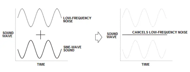
Both the active noise cancellation (ANC) and the active sound control are built into the ANC/active sound control unit. Both systems eliminate unwanted sound entering the passenger compartment. There are two microphones mounted in the headliner; one is just behind the front overhead console and the other is just ahead of the overhead rear light module. The microphones capture low frequencies entering the passenger compartment and send a signal to the ANC/active sound control unit. The ANC/active sound control unit then creates the sound wave that is sent out through the speakers to eliminate the unwanted sound.

Active Noise Cancellation (ANC)

The ANC system works to cancel the engine booming sound up to about 2,000 rpm (min -1 ). The ANC/active sound control unit receives the engine speed pulse (NEP) from the PCM and outputs a sine-wave-sound through the audio speakers to cancel the low- frequency noise from the engine. The ANC system also uses two microphones to detect and monitor the low frequency noise in the passenger compartment. The microphones feedback the noise information to the audio unit or the audio-navigation unit which adjusts the speaker output to reduce the noise. The ANC also receives the output of the door open/close signal from the MICU. Whenever any door is opened, the ANC system temporarily stops working. Each signal is sent to the ANC/active sound control unit via the F- CAN.

The ANC/Active sound control unit monitors the stereo amplifier output signals to the subwoofer, and if the subwoofer gives a sound more than the rated value, the ANC/Active sound control unit stops ANC control. This control is not for deleting bass of an audio output.
Honda Pilot. System Description Info

Active Sound Control

The active sound control is the next generation control of eliminating the unwanted sound in the passenger compartment. The active sound control has a much broader range than the ANC system. In addition to the microphones in the headliner, the active sound control also receives the output from the engine speed pulse (NEP) to provide various levels of the sound cancelling depending on changes in the engine RPM.

Self-Diagnostic Function

The ANC/active sound control unit has a self-diagnostic function to check the front and rear microphones by outputting a low frequency hum from the speakers. This diagnosis is controlled by the ANC CK2 line status (ON or OFF), and can be checked by the System Diagnostic Mode of the audio unit or the audio-navigation unit.

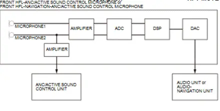
Front Microphone

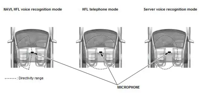
Receives a voice command or a HFT speech, and transmits them to the audio unit or the audio-navigation unit. The microphone unit consists of two microphones. One of the microphones is combined with the ANC/active sound control microphone. It detects the driver's voice and the passenger's voice separately.
Honda Pilot. System Description Info

The microphone switches the directivity according to the voltage change on HFT MUTE line.

Honda Pilot. System Description Info

Media Hub Unit

Media hub unit is a device that expands a single USB port into multiple ports and allows various devices to be connected simultaneously.

The media hub unit supports charging of USB devices by a 2.5 A electric supply.

USB Charger Unit

The USB charger unit controls an output current for charging of a USB device. The USB port D and E (CHARGE ONLY) located behind the center console are a dedicated USB charging port. The USB charger unit is based on the specification of the USB Battery Charging 1.2 (BC 1.2) that supports high-speed charging of the USB device. The USB charger unit can detect the USB device type (BC 1.2 or not), and change the charging mode automatically.

The USB charger unit is launched by turning the vehicle to the ACCESSORY mode. When you connect the USB device to the USB port D and E (CHARGE ONLY), the USB charger unit supplies the appropriate current (1.0 A - 2.1 A) to the USB device via the USB VBUS. In this case, the USB charger unit detects the electrical characteristics from the USB DATA lines. No data communication occurs between the USB charger unit and the USB device. Also, there is no connection between the USB charger unit and the audio-navigation unit.

Multi-View Rearview Camera

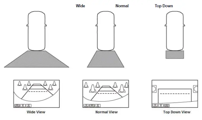
The multi-view rearview camera is a function that provides three different view images to a driver by the cameras installed in the vehicle's rear end. The view images can be changed by the user. The rearview guide lines change according to the selected view. The rearview camera is connected directly to the audio unit or the audio-navigation unit.

  • Normal View Mode The display shows the standard view.
  • Wide View Mode The display shows the wider visibility than the normal view, which helps the driver confirm any object approaching from right and left.
  • Top Down View Mode The display shows the view from the top angle of the vehicle, which helps the driver confirm the distance from any object behind.

Basic Control

The audio unit or the audio-navigation unit outputs the power source (RR CAM VCC) to the rearview camera under some conditions:

  • When the vehicle is in the ACCESSORY mode
  • When the BACK LT signal is detected (when the transmission is shifted to R position/mode)
  • When the Rear Camera diagnosis is being used in the System Diagnostic Mode

If the audio unit or the audio-navigation unit does not detect the BACK LT signal for 5 minutes, the audio unit or the audio-navigation unit cancels outputting the power source to the rearview camera.

When the audio unit or the audio-navigation unit detects the BACK LT signal for at least 0.5 seconds, the audio unit or the audio- navigation unit displays the rearview camera image. The display delays for 0.5 seconds to prevent the screen image from changing too frequently because of an incorrect shift position/mode selection.

Display audio type: Immediately after the rearview camera power source is turned to on, the display audio checks the connection with the rearview camera by monitoring the RR CAM VID line as a diagnostic function. If the display audio detects that the connection of the rearview camera is NG, the display is not changed to the rearview image even if the display audio detects the BACK LT signal.

While displaying the rearview image, the LaneWatch function cannot be used because the LaneWatch image is misunderstood as the rearview image.
Honda Pilot. System Description Info

Changing Camera Views

The audio (audio-navigation) unit sends a signal to the rearview camera via the CAMERA BIT0 and CAMERA BIT1 signal lines to change the rearview camera view when the mode icon is selected or the SELECT button is pressed while the review camera image is displayed.

Honda Pilot. System Description Info

View Mode Memorization

Whenever the audio unit or the audio-navigation unit loses power (the 12 volt battery, the audio unit, or the audio-navigation unit is disconnected, etc.), the rearview camera returns to the normal angle view. When you turn the vehicle to the OFF (LOCK) mode after selecting the top down angle, the rearview camera also returns to the normal angle view. If you change the rearview camera to the wide view, the rearview camera will maintain the view even when you turn the vehicle to the OFF (LOCK) mode.

Dynamic Guideline

When the rearview image with the guide lines is displayed, the guide lines change according to the steering angle input (when the steering rotates 90 degrees or more). The steering angle information is received from the gauge control module via B-CAN.

HondaLink911 (Display audio type (8-inch screen) )

The HondaLink is used to provide a remote service using a cell phone compatible with Bluetooth.

If the SRS airbag is deployed, the SRS unit sends a signal to the audio unit or the audio-navigation unit via the F-CAN. Then, the audio unit or the audio-navigation unit calls a PSAP (Public Safety Answering Point) automatically using a cell phone compatible with Bluetooth, and sends the vehicle location using the DTMF (Dual-Tone Multi-Frequency). The audio unit or the audio-navigation unit uses the GPS antenna for tracking the vehicle location.

Honda Pilot. System Description Info

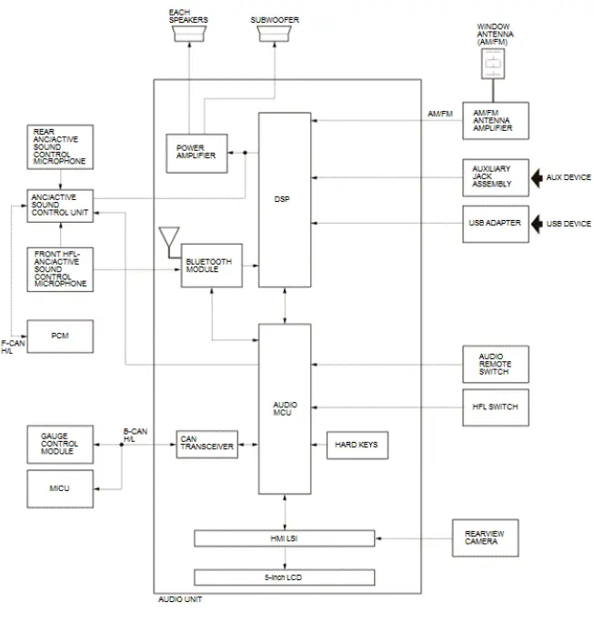
Audio System Description - System Diagram
Honda Pilot. System Description Info

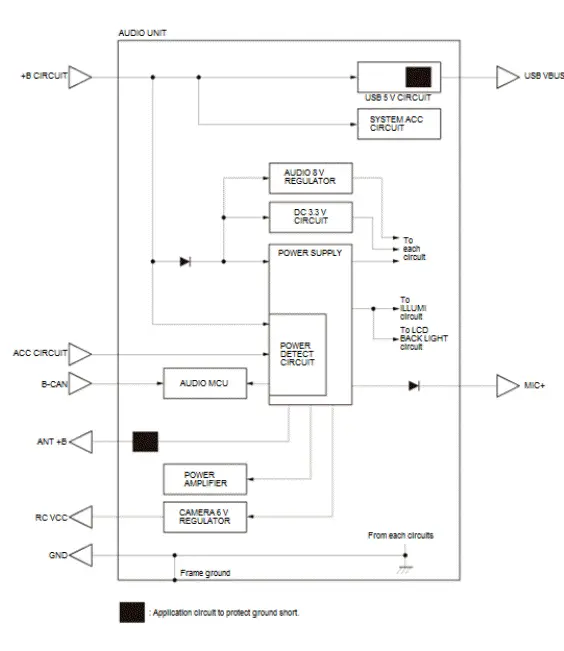
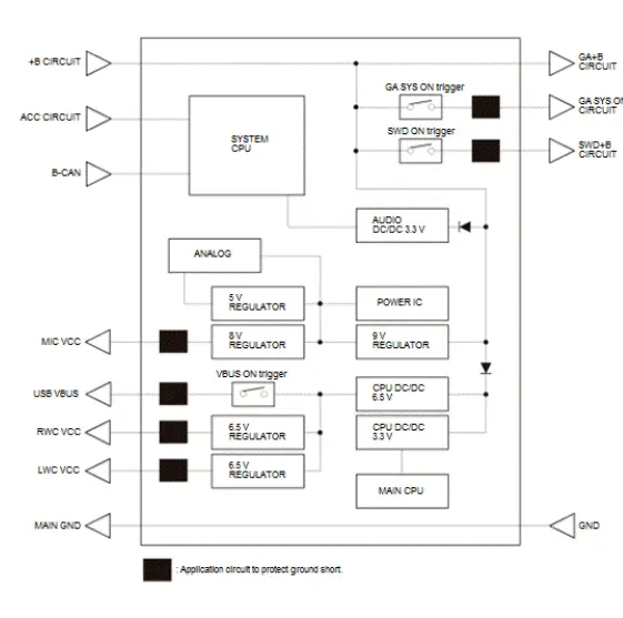
Power Supply Diagram

Honda Pilot. System Description Info

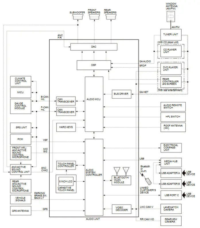
Audio System Description - System Diagram

NOTE: Refer to the navigation system section for the audio-navigation unit system diagram.
Honda Pilot. System Description Info

Power Supply Diagram

Honda Pilot. System Description Info